How Do Cable-Stayed Bridges Work?
What Is a Cable-Stayed Bridge?
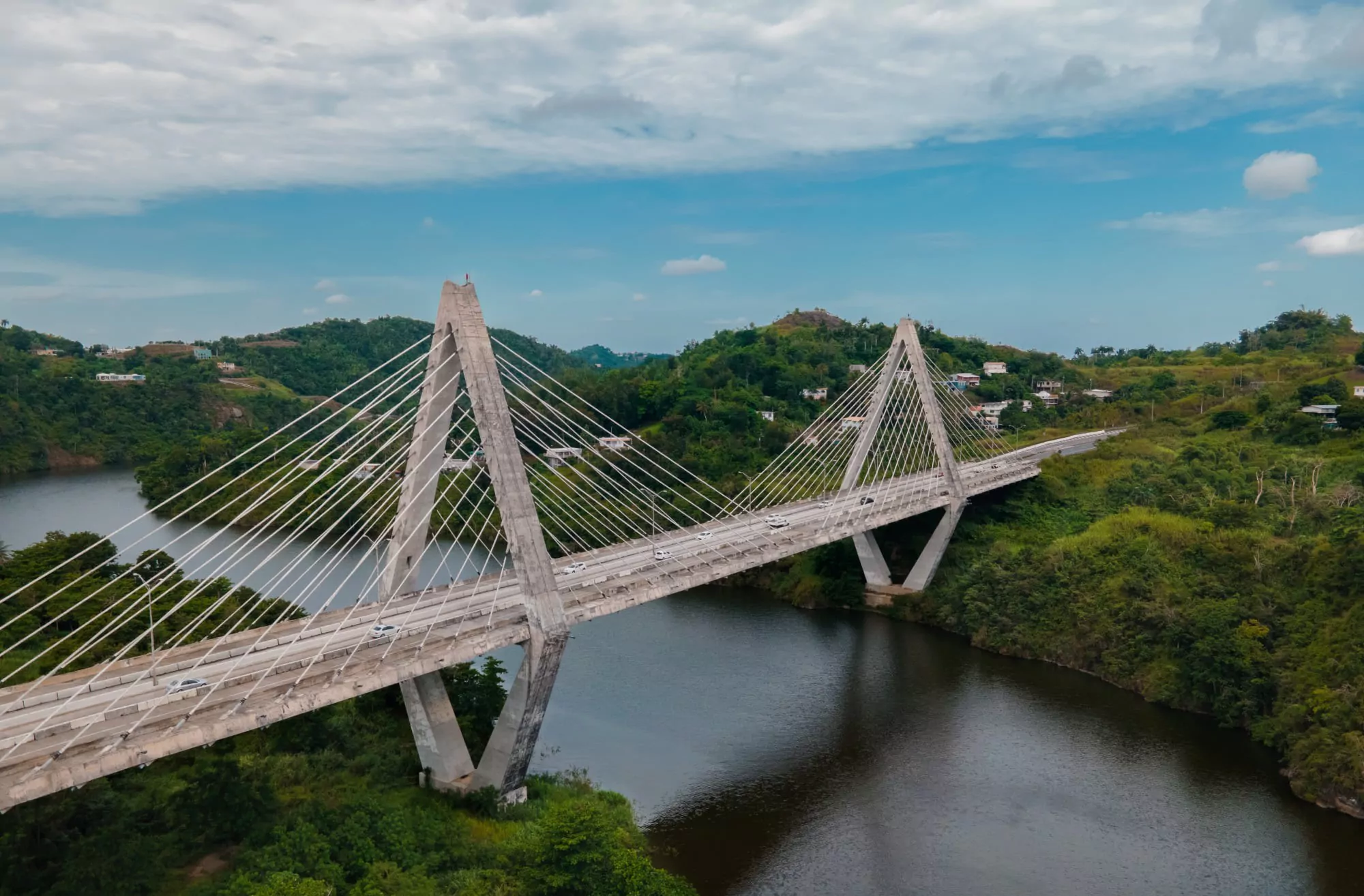
A cable-stayed bridge is a structural system where a continuous girder (the deck) is supported by inclined stay cables running directly from one or more towers to the deck surface. Each cable connects the tower to a specific point along the deck, transferring vertical loads through tension in the cables and compression in the tower and deck.
This direct connection is what separates cable-stayed bridges from suspension bridges, where the deck hangs from vertical hangers connected to a main cable draped between towers.
The system functions as a continuous beam on elastic cable supports. Stays are tensioned to counterbalance the weight of the deck and live loads, making the entire structure a prestressed system.
Because the cables pull the deck toward the towers horizontally, the deck itself carries cumulative compression along its length. This built-in prestress gives cable-stayed bridges their characteristic stiffness and efficiency.
How the cables, towers, and deck distribute loads between them is what makes the cable-stayed form work in practice.
How Does a Cable-Stayed Bridge Transfer Loads?
Vertical loads on the deck, from traffic, self-weight, and environmental forces, travel through diagonal cable stays in tension to the towers in compression.
At each tower, horizontal force components from the main span cables balance those from the side span cables, creating equilibrium that supports the full structure.
This self-balancing behavior means towers only need to resist horizontal forces from live loads like traffic and wind, not from the static weight of the structure itself.
Because all static horizontal forces cancel out at the tower, cable-stayed bridges don’t require massive ground anchorages the way suspension bridges do. The towers transfer the net vertical load straight down to the foundations, while the deck absorbs cumulative horizontal compression from the cable pull. This system, where tension in the cables and compression in the deck and towers work together, is what makes the cable-stayed form so structurally efficient for medium-to-long spans.
How Does Tension Work in Stay Cables?
Stay cables carry tensile forces along their entire length, pulling the deck upward and inward toward the tower simultaneously.
Minimal cable sag is a defining feature of the structure: when the deck deflects under load, the steel in each cable must physically stretch rather than simply change shape.
This requirement forces the cables to remain taut, which is why cable-stayed bridges are stiffer than suspension bridges and more resistant to aerodynamic instability.
That stiffness comes at a cost. Stay cables endure significant high fatigue stress, both axial and bending, because they respond directly to every load variation on the deck. Specialized materials, anchorages, and full-scale fatigue testing are standard requirements for cable-stayed bridge construction.
Compression in the Deck and Towers
Every cable pulling the deck toward the tower adds a horizontal compression force to the deck girder. These forces accumulate from both sides of the main span, so the deck carries its highest compression near the tower.
Towers absorb the vertical component of all cable loads and transfer that force to the foundations below.
The structural balance is what keeps the system stable. Compression from the main span cables on one side of the tower offsets compression from the side span cables on the other, so the tower doesn’t tend to tilt or slide under static loads. Each of these load-bearing elements (towers, cables, deck, and anchorages) has specific design requirements that determine how the bridge performs over its service life.
Key Structural Components of Cable-Stayed Bridges
Cable-stayed bridges rely on 5 primary structural components working in coordination:
- Pylons (towers)
- Stay cables
- Deck girder
- Anchorage systems
- Cable support systems
The design of each component plays a distinct role in the engineering of the full system, and decisions at the component level shape how the bridge performs under construction loads, traffic, and environmental forces.
Pylons and Towers
Pylons are the primary vertical load-bearing structures in a cable-stayed bridge, supporting the full cable array and transferring loads down to the foundations.
Common tower configurations include single column, H-frame, A-frame, inverted Y-frame, and diamond forms. The choice depends on the cable arrangement (single plane vs. double plane) and the structural demands of the span.
Most towers are built from reinforced concrete, though steel towers appear on bridges where lighter construction or faster erection is a priority.
Tower heights on the longest cable-stayed bridges can exceed 980 feet. The Millau Viaduct in France, for example, reaches 1,125 feet at the pylons, making its engineering as much about vertical design as horizontal span.
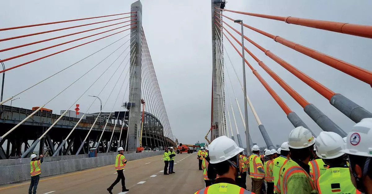
Stay Cables
Stay cables run directly from tower to deck with no intermediate hangers, making them the defining element of a cable-stayed bridge.
Modern cable systems for new structures typically contain 10 to 127 high-strength steel strands per cable, connected to the tower and deck through precision-engineered anchorages.
The 3 main cable types used today are parallel wire strand (PWS), locked coil, and spiral strand. Each strand is protected against corrosion with grease and polyethylene sheathing, while an outer high-density polyethylene (HDPE) duct shields the full cable assembly.
The modern stay cable system was developed in 1974, introducing strands as the resistant element with epoxy resin injection at the anchoring area for improved tension and fatigue resistance.
Deck and Girder Systems
Whether a cable-stayed bridge uses a steel deck, a prestressed concrete deck, or a composite (steel-concrete) deck depends on the main span length, expected traffic loads, and the cable arrangement pattern.
The structure functions as a continuous beam supported by elastic cable stays. Common cross-sections include box girders for longer spans, plate girders for moderate spans, and edge girders where aerodynamic performance matters most.
Cable-stayed decks can be lighter than suspension bridge decks because the system’s inherent stiffness reduces bending demands on the girder. This weight advantage allows engineers to use less material in the deck design, which reduces the load on cables and towers during construction and throughout the bridge’s service life.
Anchorage Systems
Anchorages secure each cable at both ends: one connection at the tower (typically a saddle or individual anchorage) and one at the deck level. Modern systems use multi-tube saddles at the pylon, which allow cables to pass through or anchor in a compact arrangement. At the deck, compact anchor blocks transfer the cable’s force into the structural girder.
Anchorages secure each cable at both ends: one connection at the tower and one at the deck level. In US practice, individual anchorages are preferred at both the pylon and the deck because they let a single stay be inspected, re-tensioned, or fully replaced without disturbing the rest of the cable system. Compact anchor blocks transfer each cable’s force into the tower and the structural girder, with hardware engineered for the high cyclic loads stay cables endure.
Anchorage engineering is tied directly to fatigue resistance and long-term durability, because every load cycle on the bridge passes through these connection points.
Cable-stayed bridges don’t require massive ground anchorages the way suspension bridges do, since the cable system is self-anchored between the deck and towers.
How these anchorages are positioned, and how many cables connect to each tower, depends on the cable arrangement pattern the bridge uses.
Cable Arrangement Patterns for Cable-Stayed Spans
Three main cable arrangement patterns define the geometry and structural behavior of a cable-stayed bridge: fan, harp, and semi-fan.
Each form produces a different load distribution, affects construction complexity, and shapes the visual appearance of the finished structure.
The choice between them is one of the most consequential design decisions in the system, influencing tower geometry, deck stresses, and construction sequence.
Fan Configuration
Fan cables converge at a single point near the top of the tower, radiating outward to the deck like spokes.
This arrangement is the most structurally efficient of the 3 patterns: because each cable meets the tower at a steep angle, a larger share of the cable force acts vertically, which maximizes the load transferred directly to the foundations.
Bridges where structural efficiency takes priority over construction simplicity tend to favor the fan design.
The tradeoff is practical. Concentrating all cable anchorages at one point on the tower creates a dense cluster that’s difficult to detail and construct. For shorter spans where fewer cables are needed, this constraint is manageable.
Harp Configuration
Unlike the fan, harp cables run parallel to each other, attached at different heights along the tower and at equal intervals along the deck.
The result is a visually clean, orderly design that many architects favor for bridges in urban or high-visibility settings.
Each cable on the side of the tower closest to mid-span carries a shallower angle than it would in a fan arrangement.
That shallower angle comes with a structural penalty. The tower must resist larger bending moments because the cable forces are spread across its height rather than concentrated at the top. Cable-stayed bridges using the harp pattern typically require stiffer, heavier towers to handle this additional demand.
Why Is the Semi-Fan Configuration Most Common?
Most modern cable-stayed bridges use the semi-fan pattern because it resolves the core tradeoff between the fan and the harp. Cables converge near the top of the tower but spread across a zone rather than meeting at a single point, which keeps cable angles steep enough for efficient load transfer while leaving enough space between anchorages for practical construction and future maintenance access.
This balance between structural efficiency and buildability is why the semi-fan dominates contemporary bridge design.
Engineers get most of the vertical force advantage of the fan without the anchorage congestion, and the tower geometry stays simpler than what a full harp pattern demands.
Once the arrangement is chosen, the construction method brings the design to life.
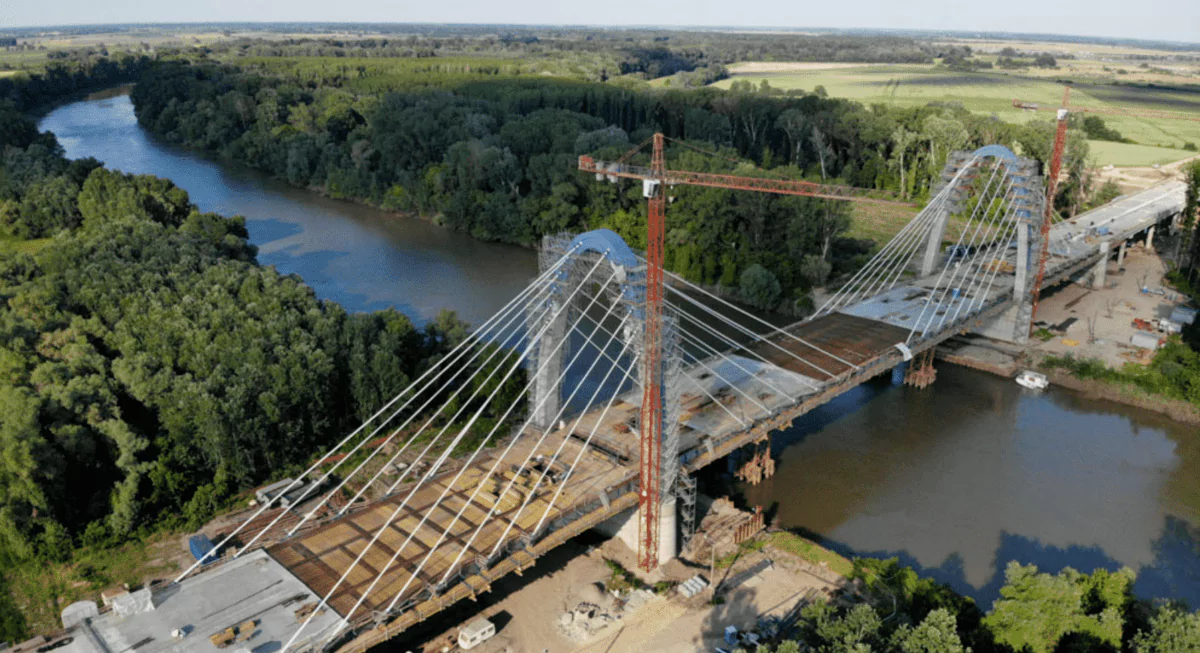
How Are Cable-Stayed Bridges Constructed?
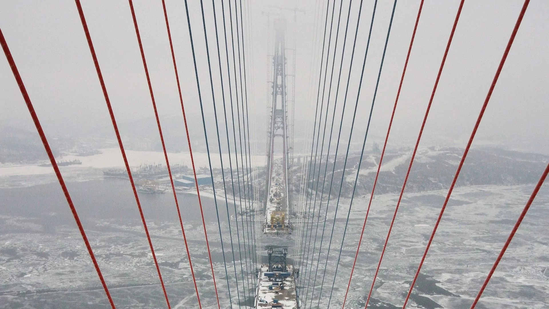
The cantilever method is the primary construction approach for cable-stayed bridges. Once the tower is built, crews install one cable and one deck segment in each direction simultaneously, maintaining structural balance at every stage.
Each new section of the deck is prestressed with concrete or steel reinforcement before the next segment begins, so the partially constructed bridge can support itself without temporary falsework below. This process repeats symmetrically from the tower outward.
Deck segments advance in both directions until they meet at mid-span and are connected, completing the continuous girder. The first cable-and-segment pair sets the geometry for the rest of the span, which is why engineering precision during early stages determines the accuracy of the finished alignment.
Eliminating the need for ground-level scaffolding makes cable-stayed construction economical for crossings over rivers, valleys, and active waterways where temporary supports would be impractical or disruptive.
Construction is just one of several areas where cable-stayed bridges depart sharply from suspension bridge design.
What Is the Difference Between Cable-Stayed and Suspension Bridges?
The difference starts at the cables.
In a cable-stayed bridge, stay cables run directly from the tower to the deck, transferring loads through a single structural element. In a suspension bridge, the deck hangs from vertical hangers connected to a main cable that drapes in a catenary curve between towers.
This distinction in force path creates different structural behaviors, span capabilities, and construction requirements.
Cable-stayed bridges are stiffer and more aerodynamically stable because their cables carry tension with minimal sag.
The deck experiences compression from the cable pull, and the entire structure is self-anchored, so no massive ground anchorages are needed.
These properties make the cable-stayed design optimal for main spans from roughly 500 to over 3,900 feet. The Changtai Yangtze River Bridge in China now holds the world record at 3,963 feet (about three-quarters of a mile), closing the gap with suspension bridges that once dominated spans of this scale.
Suspension bridges remain the choice for the longest crossings.
The Akashi Kaikyo Bridge in Japan holds the world record for suspension spans at 6,532 feet (about 1.2 miles), a range that cable-stayed structures have not yet reached.
Suspension systems require large ground anchorages to resist the horizontal pull of the main cables, and their flexibility makes them more susceptible to wind-induced oscillation.
Construction is also typically slower, because the main cables, hangers, and deck are erected in separate phases rather than the single advancing sequence used for cable-stayed bridges.
Both types demand ongoing maintenance, but stay cables present fatigue and vibration challenges that require a specialized approach.
Why Do Cable-Stayed Bridges Need Specialized Maintenance?
Stay cables have a very low fundamental frequency and minimal inherent damping, which makes them susceptible to wind and rain-wind excitation.
The range of cable lengths on a single bridge creates a continuum of natural frequencies, so almost any vibration source is likely to find a sympathetic cable. Without external dampers, cables can develop large-amplitude oscillations that accelerate fatigue damage at the anchorages and along the cable itself.
This vulnerability drives a maintenance program that goes well beyond standard bridge inspection. Stay cable maintenance services typically include periodic visual and sensor-based cable inspection, damper installation and performance monitoring, corrosion protection assessment of the HDPE sheathing and internal strands, and re-tensioning when force measurements indicate drift from the design values.
Stay cable systems are fundamentally different from post-tensioning tendons in fatigue behavior, scale, and material demands.
Confusing the 2 leads to incorrect inspection protocols and maintenance schedules.
Stay cables endure higher cyclic stress ranges, need specialized anchorage hardware, and require engineering teams with direct experience in cable-stayed bridge structures.
This distinction matters most when planning long-term maintenance budgets and selecting qualified contractors for the work.
Frequently Asked Questions About Cable-Stayed Bridges
How Long Can a Cable-Stayed Bridge Span?
Cable-stayed bridges perform best for spans between roughly 500 and 3,900 feet, outperforming cantilever designs beyond approximately 1,000 feet. Advances in high-strength steel cables and composite deck materials continue to push this upper limit, with the newest structures now exceeding 3,900 feet.
Are Cable-Stayed Bridges Safer Than Suspension Bridges?
Cable-stayed bridges are inherently stiffer than suspension bridges because their cables carry tension with minimal sag, which provides strong resistance to wind-induced oscillation. Both bridge types meet rigorous safety standards, but cable-stayed designs tend to perform better under dynamic forces within their optimal span range.
How Are Stay Cables Protected From Corrosion?
Each strand inside a stay cable is coated with grease and enclosed in polyethylene sheathing, while the full cable bundle sits inside an outer HDPE duct that may also contain cement grout or petroleum wax injection for additional protection. Regular inspection of these protective layers is a standard part of any stay cable maintenance program.
What Materials Are Used To Build Cable-Stayed Bridges?
Towers are typically reinforced concrete or steel, cables use high-strength steel strands with 10 to 127 strands per cable depending on load requirements, and decks can be steel, prestressed concrete, or a composite of both. Material choice for each component depends on span length, traffic loads, environmental conditions, and the construction method.
How Often Do Stay Cables Need Inspection?
Most bridge owners schedule visual inspections every 2 to 5 years, with more detailed assessments including force measurements and corrosion evaluation at longer intervals based on the bridge’s age and cable protection system. Bridges in aggressive environments with salt spray or high humidity may require more frequent monitoring cycles.
Can Stay Cables Be Replaced Without Closing the Bridge?
Yes. Modern cable-stayed bridges are designed so that individual stay cables can be de-tensioned, removed, and replaced while the remaining cables continue to carry the deck loads. Traffic management measures are typically required during replacement, but full bridge closure is rarely necessary for single-cable work.
What Causes Stay Cable Vibration?
Stay cables vibrate primarily because wind excitation, rain-wind interaction, and traffic-induced deck movement act on cables that have low natural frequency and minimal inherent damping, making them responsive to a wide range of excitation sources. External dampers installed near the cable-deck connection are the standard mitigation measure on modern cable-stayed bridges.
Contact Freyssinet for Cable-Stayed Bridge Engineering Services
Freyssinet brings over 30 years of cable-stayed bridge experience across North America, from new construction to long-term maintenance programs.
The team’s project portfolio includes the Arthur Ravenel Jr. Bridge in South Carolina (1,545-foot main span), the Veterans Memorial Bridge in West Virginia, and the Goethals Bridge connecting New York and New Jersey.
Contact Freyssinet’s engineering team to discuss cable system design, stay cable inspection, or rehabilitation services for your next project.
Contact Freyssinet Today!
Thank you for your interest in Freyssinet, Inc. To discuss a specific project, sign up for our newsletter, schedule a presentation, or request other information, please fill out the form below and we will contact you shortly.

🚨 Fraud alert: fake recruitment account on Facebook🚨
We have identified a Facebook page titled “Freysinnet Sustainable Tech”, that is fraudulently using a misspelled version of our company name, a copy of our logo and visual assets from several of our subsidiaries.
⚠️ This page is not affiliated with Freyssinet in any way.⚠️
The account advertises fake job opening, primarily targeting candidates from Mexico and the Philippines, for positions in Canada and the USA. Its goal is to collect personal information and requesting payments for fraudulent visa applications.
For your safety:
- Do not interact with this account
- So not share any personal, professional, or financial information.
If you have any doubts about a job offer claiming to be from Freyssinet, please verify it directly through our official websites, our Careers/Join Us pages, or by contacting us through the contact form on your local Freyssinet website.
Freyssinet will never request payment, banking information or confidential personal data as part of our recruitment process.
We’ve reported this account and are working to have it removed. Similar fraudulent accounts may appear in the future, so please stay alert.
Thank you for helping us protect our community.
🔒 Stay safe online.